Aids to Approach and Landing in Modern Aviation

Safe approach and landing in modern aviation are among the most critical phases of any flight, and aviation relies on specialized navigation aids to make these phases precise and repeatable even in poor visibility.
What are Navigation Aids?
Navigation aids, often called Aids to Navigation, are ground-based devices, systems, or signals that provide pilots with information about position, direction, distance, and altitude. They are especially important during bad weather or low-visibility conditions, where pilots cannot rely on visual cues alone.
During good weather, landings are often flown under Visual Flight Rules (VFR), where the pilot uses outside visual references, typically requiring at least about 5 km horizontal visibility and a cloud ceiling of 300 m or higher, subject to flight level and local rules. In poor visibility, however, the aircraft needs electronic guidance to stay on a safe, predefined approach path.
Ground Controlled Approach (GCA)
Ground Controlled Approach (GCA) is one of the older methods for guiding aircraft during approach and landing. In GCA, an air traffic controller monitors the aircraft on radar and provides verbal instructions to the pilot to correct deviations from the ideal path.
Two radar-based modes are used in GCA:
• Surveillance Approach Radar (SAR): Provides lateral guidance from a distant point to a few miles before the runway, aligning the aircraft with the correct direction but not providing vertical guidance.
• Precision Approach Radar (PAR): Scans the approach zone to give both lateral and vertical guidance, supporting a more precise descent path.
Although GCA was widely used earlier, it is now less common because it is labor intensive, can guide only one aircraft at a time, and its performance depends heavily on radar quality and radio communication, which can be affected by weather.
Why Instrument Landing System (ILS)?
The Instrument Landing System (ILS) has become the standard for precision approaches at airports worldwide. Compared with GCA, ILS offers:
• Automated, continuous guidance without relying on verbal instructions.
• More accurate and reliable lateral and vertical information, especially in low visibility.
• Compatibility with autopilot, enabling automatic landings on suitably equipped aircraft.
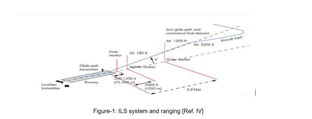
ILS uses a combination of localizers, glide slopes, and marker beacons to define a precise descent path toward the runway.
Inside the Instrument Landing System
Localizer: Lateral Guidance
The localizer provides horizontal (lateral) guidance by transmitting a radio beam along the runway centerline. It operates in the VHF band (108.10–111.95 MHz), like VOR beacons.
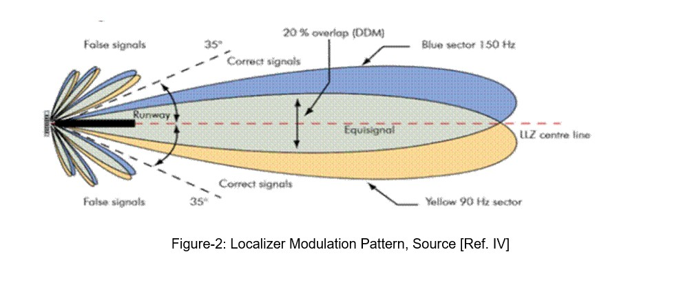
The antenna system radiates two overlapping lobes: one predominantly modulated at 90 Hz on the left side and another at 150 Hz on the right side from the pilot’s perspective on approach. The onboard localizer receiver measures the Difference in Depth of Modulation (DDM) between these signals:
• If 90 Hz dominates, the aircraft is left of centerline and must be corrected to the right.
• If 150 Hz dominates, it is right of centerline and must be corrected to the left.
• If DDM is zero, the aircraft is exactly on the runway centerline.
This information is typically displayed via the Horizontal Situation Indicator (HSI) or similar cockpit instruments.
Glide Slope: Vertical Guidance
The glide slope (or glide path) transmitter is usually installed near the touchdown zone of the runway and operates in the UHF band between 329.15 and 335 MHz. It creates a vertical guidance signal corresponding to a descent angle usually between 2° and 4°, with 3° being common.
By following this glide path indication, the pilot can maintain a stable descent rate and ensure the aircraft meets the runway at the correct point and attitude, even in low visibility.
Marker Beacons: Distance Awareness
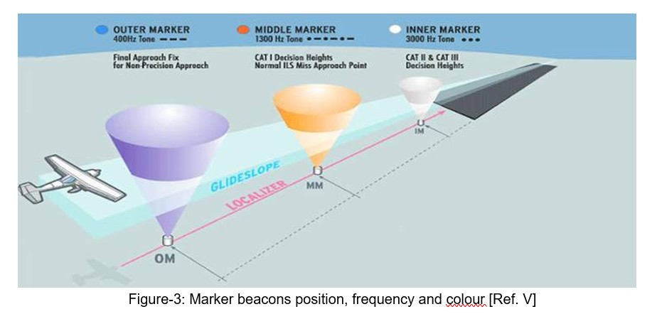
Marker beacons provide discrete distance checkpoints along the approach path, helping pilots verify their position during the final approach. Typically, an ILS installation uses three markers:
• Outer Marker (OM): About 4–7 NM (around 7 km) from the runway threshold. Operates around 400 Hz and indicates the final approach fix and glide slope intercept. It is depicted in a blue colour.
• Middle Marker (MM): About 1 km from the runway threshold. Operates around 1300 Hz and is associated with the decision height for CAT I operations. It is depicted in amber colour.
• Inner Marker (IM): Roughly 60–500 m (200–1500 ft) from the runway threshold. Operates around 3000 Hz and corresponds to decision heights for CAT II/III ILS. It is depicted in white colour.
ILS Categories and Capability
ILS performance is categorized based on decision height (DH) and runway visual range (RVR).
1. Category I: DH greater than 200 ft, with visibility around 2,600 ft and minimum runway visual range (RVR) of about 1,800 ft.
2. Category II: DH between 100–200 ft, with visibility thresholds around 1,200 ft (ICAO) or 1,000 ft (EASA).
3. Category IIIa: DH 50–100 ft, RVR at least 600 ft.
4. Category IIIb: DH less than 50 ft, RVR at least 150 ft.
5. Category IIIc: Conceptually allows operations with no DH and no RVR limit, though rare and requires highly specialized systems and airports.
Category III approaches demand not only certified pilots but also specially certified aircraft and ground systems, enabling near “zero-zero” landings.
When ILS Falls Short: Enter Microwave Landing System
Despite its global adoption, ILS has limitations. It is difficult to install in hilly or obstructed terrain and offers relatively rigid, straight-in approach paths that are not ideal for all aircraft types or airport layouts.
Microwave Landing System (MLS) is a more flexible precision approach solution for challenging terrain and slow-moving aircraft. It operates in the 5031–5090 MHz band and provides up to 200 channels globally.
Advantages of MLS
MLS offers key benefits including around 200 channels (vs. 40 for ILS), wide azimuth coverage of ±40°, glide slope flexibility from 0.9° to 20°, and better suitability for STOL aircraft and helicopters. Microwave signals are also less affected by multipath interference and adverse weather. The primary drawback is higher initial installation cost, though maintenance costs remain lower over time.
Putting It All Together
Modern approach and landing safety are built on a layered ecosystem of navigation aids. GCA provides controller-led radar guidance but is limited by workload and weather. ILS remains the backbone of precision approaches, combining localizers, glide slopes, and markers to provide predictable, repeatable lateral and vertical guidance in low visibility. MLS extends these capabilities into challenging terrain and demanding operational profiles, offering highly flexible, microwave-based precision guidance at the cost of higher initial investment.
Together, these systems ensure that aircraft can complete the final phase of flight—approach and landing—with a high degree of safety, precision, and operational resilience, regardless of weather or terrain constraints.
Learn More:
About the Author
Sagar Asmani, Sr. Engineer (Level 2) at eInfochips – An Arrow company
He has over nine years of experience in Airborne Software verification. His experience includes verification of multiple airborne software applications like Flight Display Software Application,
Flight Management Systems, 777x Maintenance, ROAAS, and so on. Sagar holds a Bachelor of
Engineering degree in Electronics and Communication from Gujarat Technological University.
Ajay Bhatt, Sr. Engineer (Level 2) at eInfochips – An Arrow company
He has over nine years of experience in Airborne Software verification. His experience includes
verification of multiple airborne software applications like Flight Display Software Application,
Flight Management Systems, ROAAS and FMS. Ajay holds a BE degree in Electronics and
Communication from Gujarat Technological University and MTech degree in Avionics from
Hindustan University, Chennai, Tamil Nadu.
Alexia is the author at Research Snipers covering all technology news including Google, Apple, Android, Xiaomi, Huawei, Samsung News, and More.